| |
VENT
SILENCERS |
| |
FAP VENT SILENCERS CHARACTERISTICS |
| |
 ACOUSTICAL PERFORMANCE
 |
| |
RELIABLE |
| |
NO PRESSURE FOR THE BODY |
| |
BODY INTERNALLY INSULATED |
| |
NOISE DISSIPATION WITH DIFFUSER & SPLITTER |
| |
LOWEST PRESSURE DROP |
| |
ACOUSTIC |
| |
35 dB (A)¯
noise reduction |
| |
¯
Mean noise reduction for the frequency range
The dB(A) Value is given Spectrum maximum from 1 to 4 kHz. |
| |
|
| |
 |
| |
|
| |
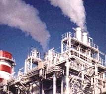
APPLICATION |
| |
FAP silencers are dedicated to reduce the
noise generated by the compressed gaseous fluid blow off
air, steam, gas (nitrogen oxygen and soon...). They can be
installed down stream to any system discharging to the
atmosphere any compressed fluid : valves, ejectors and
soon.... |
| |
|
| |
Design |
| |
Absorption type silencer employing a single
stage diffuser and containing an acoustic core to decrease
high frequency noise. |
| |
|
| |
Construction |
| |
All-welded construction of sheet and plate
steel. Absorption material appropriate for operating
conditions. Exterior surfaces are prime coated. Flanges are
drilled to match 150 lb. american standard flanges. Side
connections, mounting brackets, or special paint available
at extra cost. |
| |
|
| |
DESCRIPTION |
| |
FAR Silencer totally welded construction
Quality of steel used is depending on characteristic of
fluid and technical data (pressure temperature). |
| |
|
| |
Thermal expansion |
| |
Fixings of the silencer represent a fixed
point. For high temperature service thermal growth of the
upstream pipe has to be absorbed by special system to be
supplied upon request. |
| |
|
| |
OPTIONS |
| |
Flanges, counter flanges, joints, bolts,
supports, drain, special materials, special paints, rain
protection, dismantable,expander. |
| |
|
| |
PRINCIPLE |
| |
FAR silencers are based two principles of
noise reduction
l
Un noisy and controlled expansion of the fluid.
l
fliss pat on of generated noise. |
| |
|
| |
OUTLINE TABLE |
| |
| NO |
Model |
A |
B |
H |
W[kg] |
| 1 |
S-2900 |
750 |
750 |
2650 |
1400 |
| 2 |
S-3250 |
1075 |
1075 |
2650 |
1900 |
| 3 |
S-3550 |
1400 |
1400 |
2650 |
2500 |
| 4 |
S-3400 |
750 |
750 |
3150 |
1500 |
| 5 |
S-3750 |
1075 |
1075 |
3150 |
2000 |
| 6 |
S-4050 |
1400 |
1400 |
3150 |
2800 |
| 7 |
S-3900 |
750 |
750 |
3650 |
1600 |
| 8 |
S-1075 |
1075 |
1075 |
3650 |
2300 |
| 9 |
S-4550 |
1400 |
1400 |
3650 |
3000 |
|
| |
note 1: Size in mm, weight in kg
note 2: these data could be changed dur ng the process des
gn and niet size. |
| |
|
| |
CHOICE CRITERIA |
| |
|
| |
AERODYNAMICAL DATA |
| |
Fluid type, pressure, temperature upstream
the blow down system and permissible counter pressure at the
entrance of the silencer.
Max. instantaneous gas flow through the silencer or the gas
volume to be discharged, duration of the discharge and time
of opening of the valve.
Connecting pipe diameter for the silencer. Position and
installation drawing for the silencer and any complementary
information.
Nazzle section for system of blow down. |
| |
|
| |
ACOUSTICAL DATA |
| |
Noise reduction or residual sound pressure
level required.
Position of measurement point in regards to discharge pipe. |
| |
|
| |
SILENCER SELECTION |
| |
FAR will determine the best silencer
consider ng the requested sound reduction, gas flow,
pressure drop or counter pressure permissible and authorized
sizeE |